In my previous post I wrote about a circuit that would change it's output depending on what was the spice simulations DC sweep range. Today I investigated the circuit a little and I was able to remove lots of components that didn't affect the bug and this is the resulting circuit:
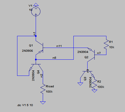
Schematic
Spice simulation results of the changed circuit:
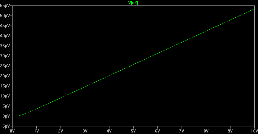
DC sweep from 0V to 10V
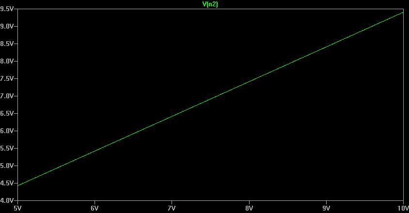
DC sweep from 5V to 10V
The next step was to build this circuit using real transistor and measure what the real output is.
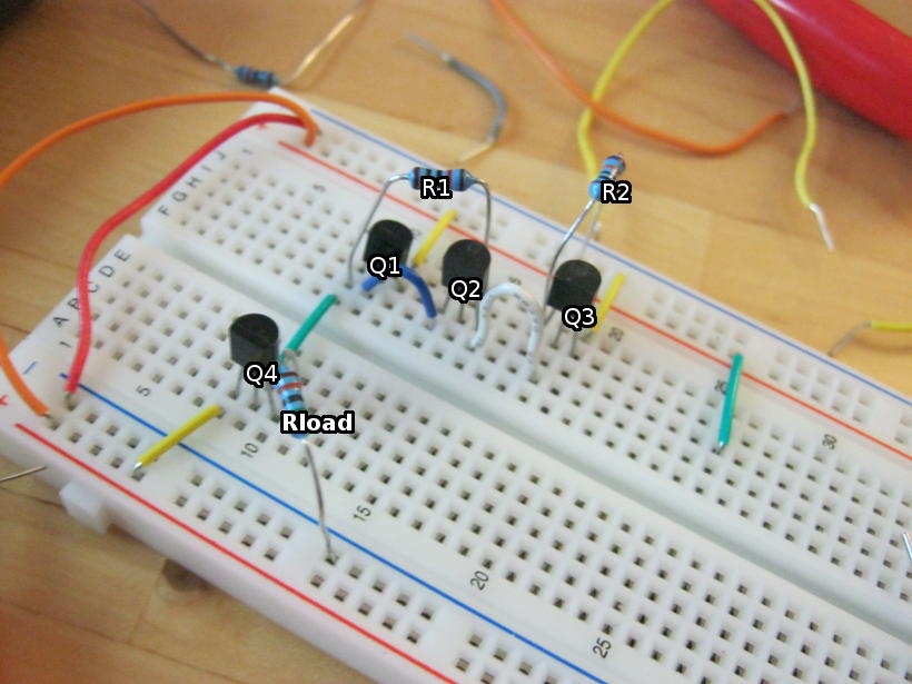
Circuit built on the breadboard
First I tried to power the circuit from 9V battery and the measured output was 7.5V(The reason I use batteries is because I don't have a proper power supply, I have the components to make one using LM317 but I haven't found time yet). Spice simulated that output voltage would be 8.5V(or 50µV), but the 9V battery I'm using isn't exactly new and adding 300Ω resistor to series with the voltage source to model the internal resistance of the battery gives output of 7.5V at 9V input. I also tried to get the output to stay at the 0V and I found out that if I power the circuit with even emptier 9V battery that gives only 4.7V at the output and touch lightly with a grounded wire to the base of Q2, output voltage stays near 0V for few seconds and then rises quickly back to 4.7V. I couldn't really capture this in a picture so I took a video instead:
So in the end Spice was sort of correct. The circuit does have one stable state when the output is almost supply voltage and other metastable state where output is near 0V. The 0V state might be stable in the simulation, but small differences in the transistors or inaccurate models in the simulation might make this state only metastable.