I've been playing with the electronic circuit genetic algorithm design program. I have tried to make some stable bandgap voltage references, so far results have been promising, but not very good. None of the resulting circuits could be used in a production, except if you don't care much about the temperature stability.
One circuit that seemed good when it was evolved was this one(No circuit diagram because I'm lazy):
1 2 3 4 5 6 7 8 9 10 11 12 13 14 15 16 17 18 19 20 21 22 23 24 25 26 27 28 29 | |
When input is swept from 4V to 10V, with step of 0.1V. This is the output voltage:
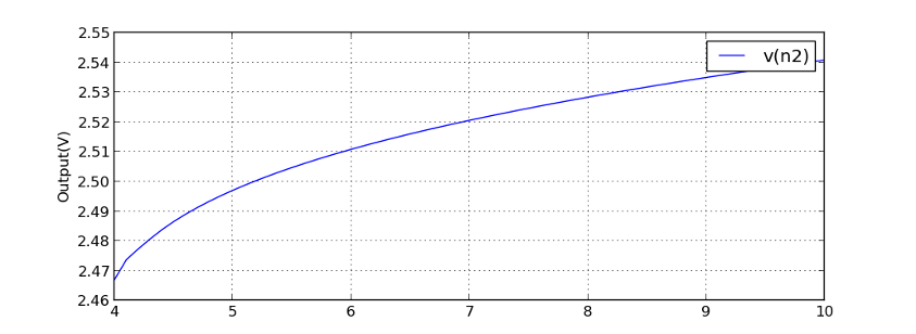
Spice command: dc Vin 4 10 0.1
Looks good, but when output is swept from 0V to 10V this is the result:
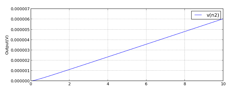
Spice command: dc Vin 0 10 0.1
Note the y-axis values. After changing only the range of the simulation spice returns completely different results for the whole range. I investigated this a little and when the DC sweep starting value is lower than 3.8441V spice returns the almost zero output value. If starting value is 3.8442V this is the output:
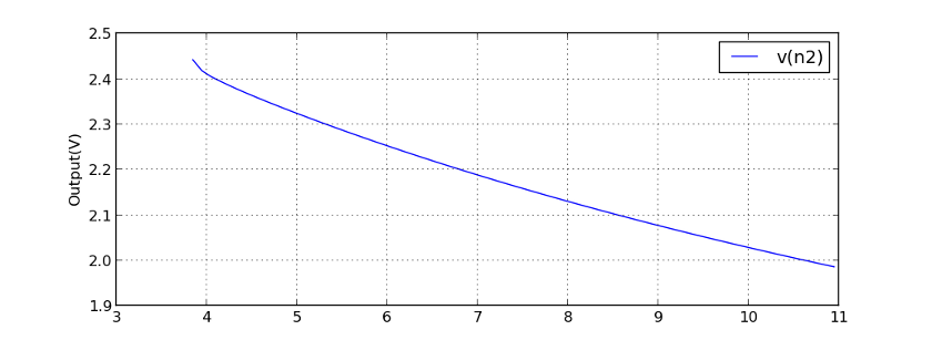
Spice command: dc Vin 3.8442 11 0.1
For the starting values 3.8443V and higher spice returns same results as in the first picture. I don't know which output is really correct and I don't really care that much as the circuit wasn't that good anyway, but if you decide to build this circuit let me know the results.
New bandgap voltage reference
For the next simulation I changed evolution's goals to avoid spice bugs. I varied the dc sweep starting and ending values a small amount for every spice simulation. I also learned from my last post and added input current measurements, more measurements with different load resistances and measurements with different temperatures. I also changed goals so that I didn't check what value output voltage was, but only scored circuits for the stability of the output voltage and let the evolution to decide what is a easy to build voltage reference, but because permanent 0V on the output would also be stable I added a check that output voltage is higher than 1V. I also added a transient simulation that simulates a circuits response to 10V step in input voltage. Transient response isn't that important, but its reason is avoiding bugs. Transient simulation is harder than dc sweep and if spice doesn't know how to simulate a transient response it sure doesn't know to simulate the dc sweep. And if you're wondering why these changes aren't in the github, it's because I just hard coded everything and it can't be currently used to simulate anything else. I will be adding these changes too, but I need to make sure first that the program still works.
I decided to abort the simulation after 30 minutes to avoid overfitting and because the resulting simulations looked good.

Generation 50. Schematic as the program designed it. Output is on the collector of Q3
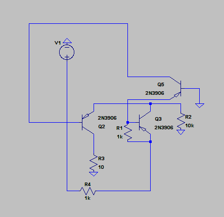
Unnecessary parts removed. I later realized that R3 can also be removed. R2 is the load resistor
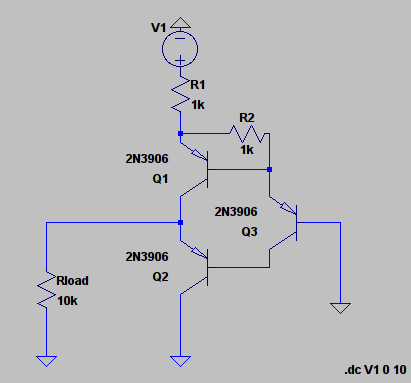
Previous circuit redrawn and R3 removed. Labels changed.
Simulation results, output voltage is 1.4V, which is about 2*Vbe of a bjt transistor.
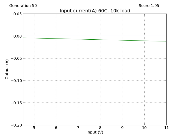
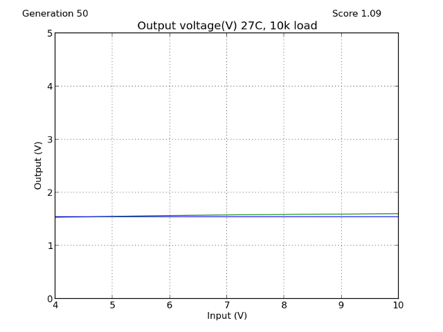
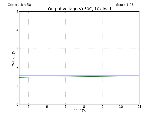
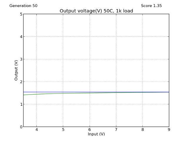
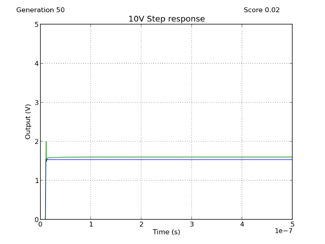
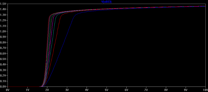
Rload stepped from 1k to 10k with 1k step. Output begins to fall if load is less than 1k.
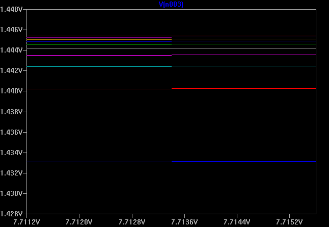
Zoomed view of previous plot
The simulations look very promising, especially the constant voltage despite the load resistance, which I had problems with last time. Input current is also small and transistors should not break. Because the simulations looked so good I decided to build this circuit and test it's output.
Built with real components:
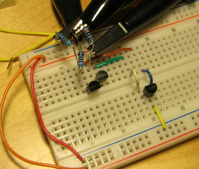
I changed the 800 Ohm resistors to 1k Ohms because I didn't have 800 Ohms resistors. Load resistor is 10k Ohms
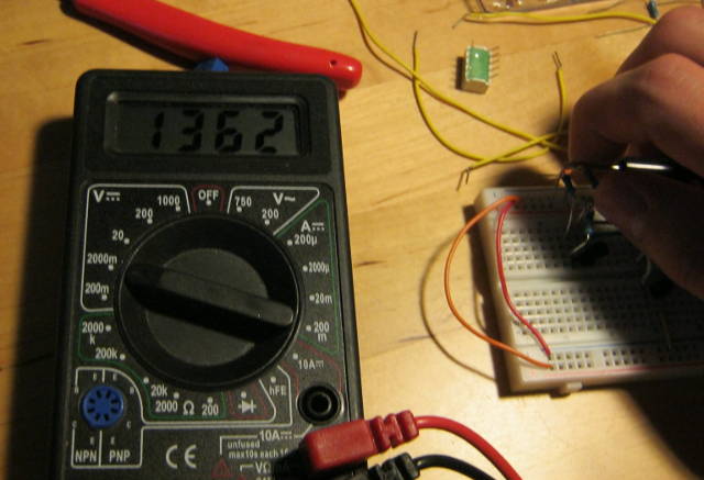
Measured output: 1.362V at room temperature(20° C) when powered from 9V battery, Spice simulated 1.42V.
I measured the temperature coefficient by placing the circuit in the freezer for few hours.
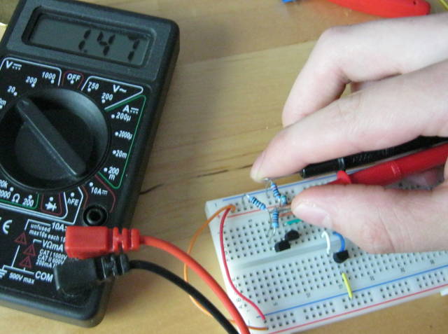
Measured output: 1.47V at about -20°C again powered from 9V battery. Taking pictures and using the multimeter same time is hard.
Temperature coefficient is about 3mV/°C, not very good as voltage reference but might be okay for some applications where temperature doesn't change that much.
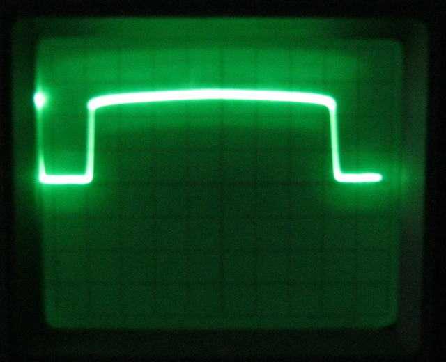
DC sweep, input is 0V to 10V triangle wave, 0.5V/div
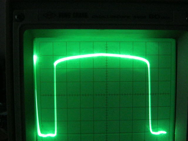
Zoomed, 0.2V/div, there was some DC offset in the input triangle wave so the bottom isn't actually ground
As you can see above the circuit really works as a voltage reference. I think it has a very good performance considering that it uses only three transistors, at least it's better than anything I could have designed using three transistors.
Error due to the input voltage is about 20mV/V.
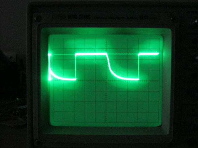
10V step input response, 2µs/div, 0.5V/div
Transient behaviour is good. Output voltage rises very quickly, quicker than I can measure with my 60Mhz oscilloscope, but it falls slowly.
Output voltage was little off from the simulated value, but transient response and dc sweep looked very much like in the simulation. I tried to change some of the transistors, but it didn't change output voltage much. Overall considering that the circuit uses only three transistors and the computer made it in 30 minutes it's behaviour is good.