Ionizing radiation is something that almost anyone finds exciting (or scary) and I've also been for long wanted to build a Geiger counter. Unfortunately Geiger tubes have usually been too expensive to seriously consider buying them just for a hobby project. But I found out that sovtube sold soviet cold war era Geiger tubes only for a couple dollars. I bought one CI-22BG tube and one CI-3BG tube for total of 16€ including shipping from Ukraine to Finland. The site itself didn't really convince me payment via Paypal failed because of invalid seller email address and gmail warned me that order confirmation e-mail might not have come from the address it claimed. However, I got both of the tubes and they seemed to be okay.
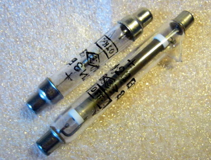
Two Geiger tubes. Longer one is CI-22BG and smaller one is CI-3BG.
Because I didn't have anything radioactive to test my Geiger counter, I also ordered a piece of radioactive Fiesta dinnerware from ebay. Red Fiestware used to have uranium oxide in its glaze that was radioactive enough to be detected with a Geiger counter.
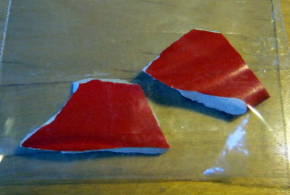
Two pieces of slightly radioactive fiestaware.
Geiger tube needs a high voltage, my tubes need 400V, to function. We need also a microcontroller to count the events and maybe a LCD to display the output. Also no Geiger counter is complete without a buzzer. I decided to also have USB port now that I included a microcontroller.
Schematic

Circuit schematic of the Geiger counter. Click for bigger view.
The device can be powered by USB or external voltage source. Circuit on the upper left corner, which was copied from this Stack Exchange answer, is responsible for choosing the right power supply. It will use USB if it's connected, otherwise it'll connect the external power supply. IC1 is step up converter that will increase supply voltage to 7V, or pass it through if it's already over 7V. This will allow the device to work with even 2V external voltage. IC3 is 5V low dropout regulator, that will regulate 7V to 5V for microcontroller. At the center there's the high voltage supply that will output 400V from 7V input. It runs in a closed loop with microcontroller adjusting the duty cycle to get a stable output voltage.
Normally Geiger tube will pass only a small leakage current, but when ionizing radiation hits the Geiger tube some of the gas inside the tube is ionized which will allow higher current through the tube, 4.7M anode resistor R10 limits this current to a safe value. This current will raise voltage at the base of T4 turning it on which pulls the detect net low. Then the microcontroller interrupts at the pin change and counts one event.
High voltage supply
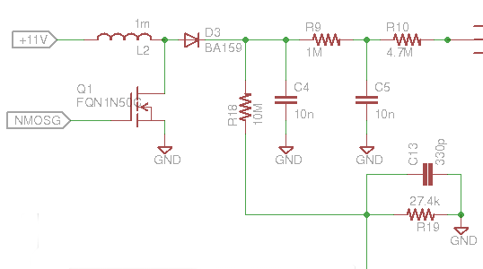
High voltage supply schematic. R18, R19 and C13 are for feedback to microcontroller. R9 and C5 are used to filter the output and R10 is Geiger tubes anode resistor.
Because I wanted the device to work with USB the input voltage is 5V and this needs to be raised to 400V. Many other Geiger counter high voltage supplies use some topology that includes a transformer, but because transformers are big, heavy and expensive I didn't want to use them. At first I wondered if ordinary boost DC/DC converter running in discontinuous mode would give high enough voltage gain, so I made some test on a breadboard and with right components I managed to get 444V from 5V input voltage, which is more than enough to drive a Geiger tube. It could have gone to even higher voltages, but I was already over the SF16 diodes 400V breakdown voltage and 450V was upper limit of Geiger tubes working voltage. With a better layout on the PCB output voltage can reach over 500V.
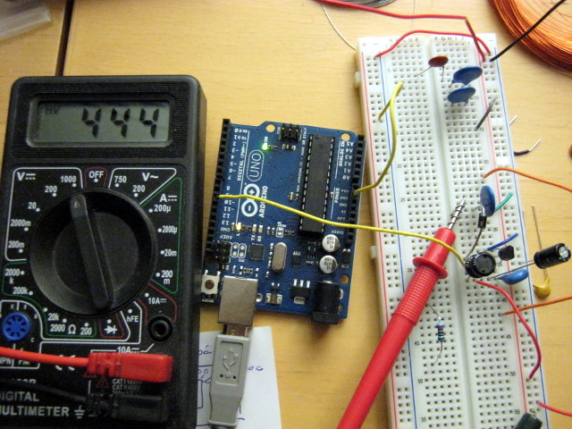
Testing HV supply with 5V input voltage. This circuit uses SF16 diode, which should have a breakdown voltage of 400V, but looks like it can handle a little bit more. Mosfet is FQN1N50C.
I tested several different transistors and diodes. For mosfets, on resistance and switching speed were most important parameters. I didn't manage to get the only high voltage BJT I had, MSP44, to work at all. Because boost converter works in discontinuous mode, reverse recovery time of diode is important to minimize leakage. 1N4007 diodes were garbage at this application, BA159 was okay, SF16 was even better, but it's breakdown voltage was only 400V. Highest output voltage was with Cree CSD01060 600V silicon-carbide schottky diode. Because it's schottky diode it has only neglible reverse recovery time. Difference between 1N4007 and CSD01060 was about 100V, which is quite significant. With schottky diode output had hardly any noise and with 1N4007 noise was so bad that Geiger tube event detection circuit triggered every time mosfet was switched. I ended up using BA159, because of its high breakdown voltage and small footprint compared to CSD01060. Schottky can also have bigger reverse leakage than ordinary silicon diode. It's important in this application to keep it small, because available current at the output is already very small.
Switching transistor had an even bigger effect:
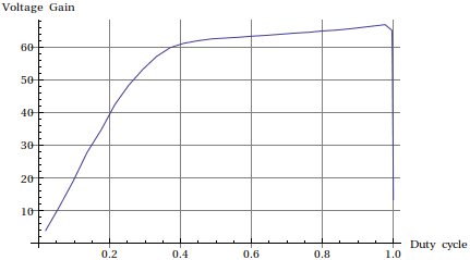
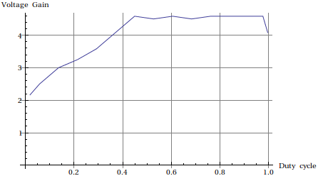
Voltage gain as a function of duty cycle with AOD3N50 mosfet. Input voltage was 1.2V for these tests. Voltage gain is low, because gate voltage was only 5V. Mosfets on-resistance at that gate voltage is too high to discharge the inductor fast enough, using higher voltage would have most probably raised the voltage gain.
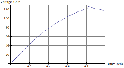
Same with FQN1N50C mosfet. Output voltage was very unstable at high duty cycles.
I couldn't get MSP44 BJT to work at all.
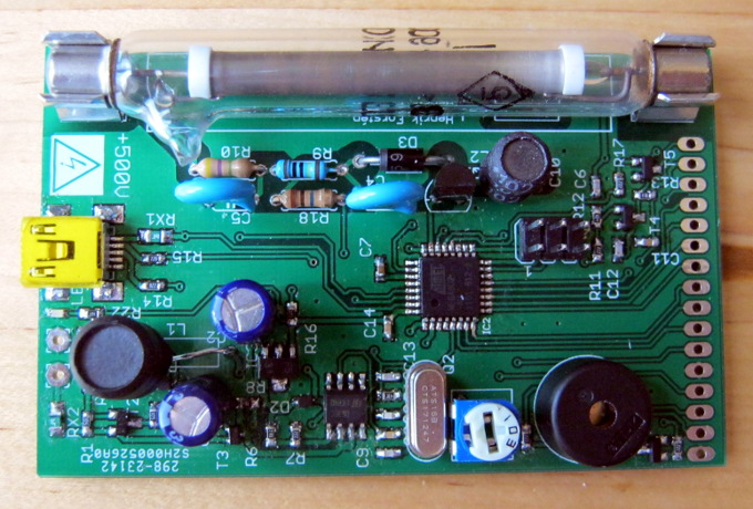
PCB
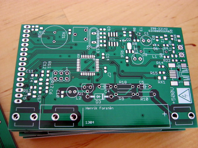
PCBs from iTead. All of them looked fine. LCD connection and Geiger tube mount limited the minimum size of the board, so I had plenty of room to place the components.
PCB was designed with Cadsoft Eagle and manufactured in China by iTead, they were the cheapest PCB supplier I found. I decided to use mostly SMD components wherever possible, resistors and capacitors are in 0603 package. I was little sceptical if I would manage to solder them with my not so good tools, but it in the end it wasn't hard at all. I might even consider using 0402 package on my next projects.
I made the high voltage side using through hole components, because all of the SMD resistors I looked at claimed a maximum working voltage of about 200V, when I needed at least 400V.
Total cost was about 50€ including shipping costs. PCBs cost 21€ including shipping and for that price I got 12 of them. Atmega8U2 was single most expensive component costing 3€, other components together cost about 15€ and the Geiger tubes were 16€. Looking at the prices for Geiger counters at eBay, I don't think it was very expensive and building at least 10 at the same time would about halve the price.
Design is open source. Hardware design, PC software and microcontroller software are available at Github.
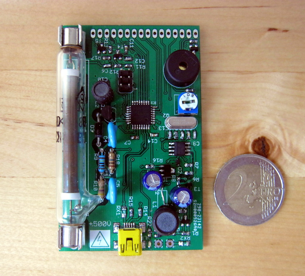
With components and 2€ coin for scale. I had to change the inductor on bottom right corner, because the inductor that I originally chose turned out to have so much coil noise, that it was almost louder than the buzzer.
Testing the Geiger counter
Fiestaware piece I have shows about 700 counts per minute, depending slightly on how close to the tube I hold it. Background radiation level is about 10 CPM. I don't know how to convert CPM to any SI units with this tube, but according to the eBay seller I bought the fiestaware piece it should have radioactivity of about 20-30µSv/hr. Background radiation level should be about 200-400nSv/hr. Ratio of these numbers is approximately 80, which is about the same as I measured.