Boundary Scan Description Language (BSDL) files are provided by many electronic component manufacturer for testing the pins of the microcontroller, FPGA or any other bigger device with JTAG. Even though they are meant for JTAG testing they can be used to generate device symbols for schematic designs, because these files list pins of the device and their locations on the chip.
Eagle has an ulp file that can generate the symbol from BSDL and I have used that with Eagle, but I wasn't aware of any similar tool for KiCad so I made my own. It's still a beta version so report any bugs you find.
Automatic generation is not perfect and some errors are common. BSDL files are not meant for this and often some unimportant pins for JTAG are left out, for example input voltage and ground pins, because testing them with JTAG is not possible. Also listed pin names are usually the first function of the pin, but in many devices one pin can have many alternate functions. Still BSDL files usually have most of the pins and user only needs to check that everything is correct and add alternate functions to pin names if needed. Creating a big BGA device symbol using BSDL files is significantly faster than doing everything by hand even if some manual checking is needed.
You can access the tool here.
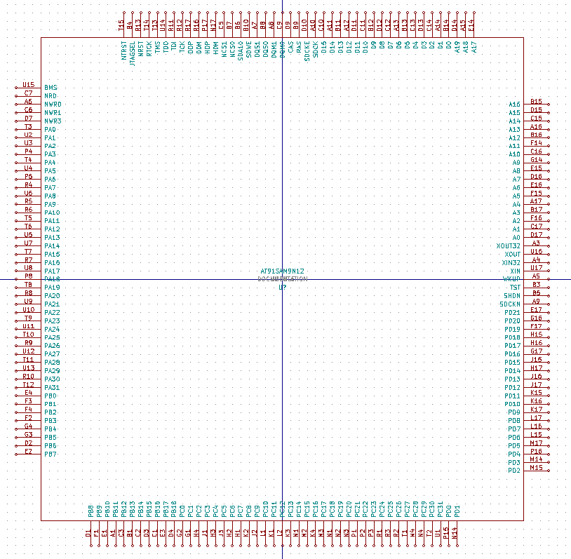
Automatically generated AT91SAM9N12 microcontroller symbol. Input voltage and ground pins are missing because BSDL file didn't list them. Other than that pins are correct.