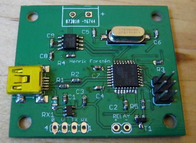
Almost finished controller board. This one was soldered by hand.
Introduction
Nowadays many of the most "exiting" chips come only in leadless packages, such as BGA and QFN which are hard or impossible to solder just by soldering iron, because leads are under the chip where they can't be reached. These kinds of chips are usually soldered using reflow soldering. In reflow process solder paste is used instead of solder wire. It contains very small balls of solder in flux, diameter of the balls is just few micrometers. First this paste is put on the contact pads, then components are placed on the pads and whole board is heated in reflow oven where solder balls in the paste melt and attaches the components firmly in place.
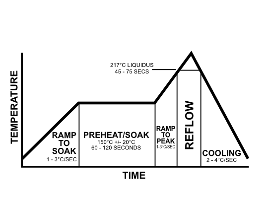
Temperature profile in reflow soldering. Source: Wikipedia
For the solder paste to work correctly temperature of the oven must follow correct temperature profile accurately. If the temperature rises too quickly it can damage the components and if the temperature rises too slowly, too much flux can evaporate and the components aren't soldered reliably.
Real reflow ovens are usually expensive, like many other manufacturing tools, but ordinary toaster ovens can be used in reflow soldering with few modifications. They are much cheaper than real reflow ovens, but temperature cannot be set programmatically or accurately. External controller board can be used to control these ovens.
Reflow oven controller
Toaster oven reflow controllers have been done before many times (for example 1 and 2). I wanted to make a simple and cheap controller that wouldn't use outdated parts. Instead of buttons and dedicated display, it should use USB port for setting the temperature profile and monitoring the temperature if needed. This would be cheaper to make and easy to use. If the computer isn't connected, it should be able to be switched on by just connecting the power supply, load the temperature profile from non-volatile memory and run without user intervention.
Because the oven gets very hot, it's not possible to add any electronics inside it. Controlling is done by switching the power on and off rapidly with solid state relay that is connected on extension cord. Temperature is measured using thermocouple inside the oven. Microcontroller will read the temperature and output PWM signal for the solid state relay which can be used to accurately control the temperature of the oven.
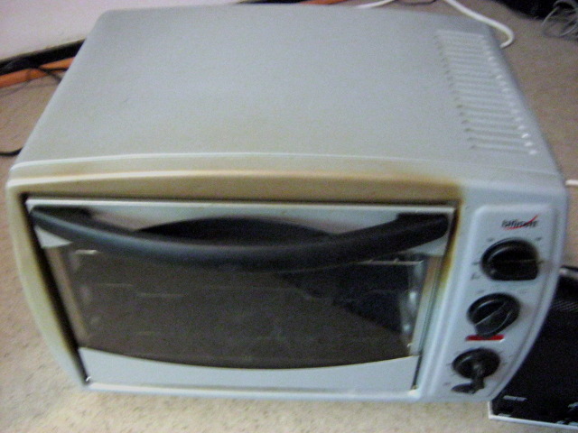
1380W Toaster oven with convection. Bought second hand for 20€.
I decided to use ATmega8U2 microcontroller, because I'm familiar with AVRs and this is the cheapest AVR with hardware USB support.
Because oven can get pretty hot I needed to use thermocouple for measuring the temperature, instead of cheaper temperature sensors ICs. I use MAX31855 as a thermocouple-to-digital converter. This is the most expensive component in the board costing 6.21€ at Digikey, even the solid state relay from dealextreme was cheaper costing only 5.08€.

Schematic. Click for bigger view.
Unfortunately I made some mistakes with the PCB and wired the USB connector pins in reverse order. One trace was also left partly unrouted, when I accidentally removed part of it in Eagle before generating the gerber files. I didn't have tools to fix the USB connector traces, so I just cut them out and soldered an USB cable on the board. Missing trace was replaced with enameled wire.
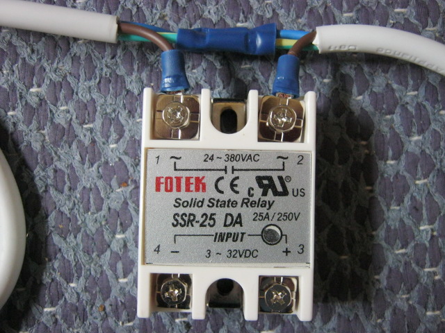
Extension cord with solid state relay before adding tape.
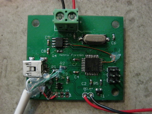
Board with USB cord and wire to fix the unrouted trace.
Firmware
Program reads the current temperature of the oven from MAX31855 chip through SPI, at the same time the chip also gives room temperature and signals if there is any faults with the thermocouple. State machine is used to get the current reflow state and target temperature. Every second current and target temperatures are outputted through USB port to computer for logging if it's connected.
On the computer side the microcontroller looks like a serial port and commands can be sent and read with any serial port program. If computer isn't connected microcontroller starts the reflow automatically with profile loaded from EEPROM.
PID controller is used to adjust the relay PWM signal, but because the oven responds very slowly the derivate component of the PID isn't very useful and the controller works really as a PI controller. This microcontroller, like many other cheap microcontrollers, doesn't have native floating point unit, so all arithmetic is done without floating point numbers to save program space.
Microcontroller has 8kB of program space and code uses 92% of it. Most of it is taken by USB library and printf function and the control code takes only about 10%.
Testing
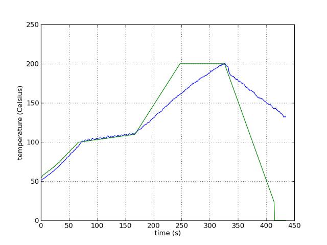
Controller testing with a made-up temperature profile. Green is the target temperature and blue is the current temperature. Relay was fully on between 170 - 320 seconds, but oven couldn't heat fast enough to reach the target. Oven door was opened after the peak was reached to speed up the cooling.
Controller works like it should, but the oven doesn't heat fast enough to accurately follow the proper reflow soldering profile. This should be fixable by adding some insulation to the oven. Currently it has only small empty space between outer case and oven chamber.
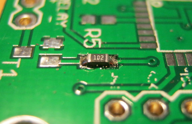
Reflow soldered 0603 resistor.
Reflow soldering works, but I have only tested with 0603 resistors right now. Quality is good, much better than I'm able to solder by hand. Also if the component isn't placed straight, surface tension of the solder pulls the components almost perfectly straight when it's reflowed.
Board design and microcontroller source code is available at github. The PCB on github has USB connector wired correctly and all the traces routed.
Bill of materials
| Component | Cost/€ |
|---|---|
| Oven, used | 20.00 |
| PCBs, 10pcs | 7.78 |
| MAX31855 thermocouple-to-digital IC | 6.21 |
| Solid state relay | 5.08 |
| ATMega8U2 microcontroller | 3.05 |
| Thermocouple | 1.59 |
| 3.3V regulator | 0.33 |
| Extension cord | 3.00 |
| Other components | about 2.00 |
| Shipping+VAT | 9.02 |
| Total | 58.06 |