Introduction
Frequency modulated constant wave (FMCW) radar return signal from target is a sine wave and its frequency depends on the distance to target. Phase of this signal is very sensitive on the distance to the target.
By analyzing phase variation of the radar return signal very small movements can be resolved. Movements less much smaller than wavelength of the radar can be resolved, but downside is that two different targets can't be resolved any better than radar normally can (tens of cm to meters).
If you aren't interested in the mathematics about how this works you can scroll down and watch videos instead.
Mathematics
Let \(x(t)\) be the transmitted linearly increasing frequency sweep from \(f_c -B/2\) to \(f_c + B/2\) in \(t_s\) seconds:
\(f_c\) is the sweep center frequency, \(B\) is sweep bandwidth and \(t_s\) is sweep length. Amplitude of the signal is not important in this analysis and is set to 1.
Transmitted signal travels at speed of light and reflects of the target at distance \(r\) and is received after time \(\tau = \frac{2r}{c}\), where \(c\) is speed of light.
Received signal is mixed with a copy of the transmitted signal which results in difference and sum of frequencies of the signals. Sum term is too high frequency (about twice the carrier frequency) and is filtered out. Difference term is low frequency, usually few kHz, and contains the information about the target:
First term with \(t\) dependency is frequency of the signal and last two terms are phase. When Fourier transform is taken frequency of the signal can be found out giving the distance to the target. Resolution of radar as defined by minimum distance of two targets such that they are detected separately follows from the resolution of Fourier transform. Length of Fourier transform is same as sweep length \(t_s\). Resolution of discrete Fourier transform is sampling frequency \(f_s\) divided by number of samples \(N\): \(\Delta f = f_s/N\). Because the signal is \(t_s\) long, there are \(f_s t_s\) samples. Frequency resolution can be improved by increasing the sweep length, but increasing the sweep length also decreases the frequency from the target. Changes balance out exactly and range resolution is independent of the sweep length:
The phase terms also contain information about distance to target. \(\pi \frac{B \tau^2}{t_s}\) term is called residual video phase term and due to \(\tau^2\) term is very small and can often be ignored. Second phase term on the other hand can be expanded as:
where \(\lambda\) is the wavelength of the sweep center frequency. Changing the distance to the target by half wavelength is enough to wrap the phase around. Phase noise of the radar determines the resolution the phase can be determined, but usually it should be possible to detect phase within few degrees.
At 5.6 GHz wavelength is 54 mm and assuming that minimum of 1 degree change in phase can be detected it gives the minimum detectable movement of 75 µm.
One drawback of using phase is that while it can sense small changes in distance, it can't resolve closely spaced targets any closer than is possible by analyzing the frequency term since Fourier transform is needed to get the phase. This means that if two equally reflecting targets are moving in opposite directions close together, then their movements cancel each other and radar doesn't detect either of them.
In video above I'm moving the antenna a short distance and in the upper right corner there are plotted raw signal from ADC and Fourier transform of the same signal. Phase of the signal changes very rapidly, but the frequency stays unchanged at this scale due to the limited resolution of the radar.
Breathing and heartbeat detection
Above is a short video of me sitting still facing the radar. First I'm breathing normally and then I hold my breath for short time.
Radar sends sweeps with linearly increasing frequency at 1 kHz repetition frequency. For every sweep the sampled signal is Fourier transformed so that returns from targets at different distances can be separated. Then phase of one of the FFT bins at distance where I'm sitting at is saved. Same processing is done for all of the sweeps and unwrapped phases are plotted to give the plot on the video.
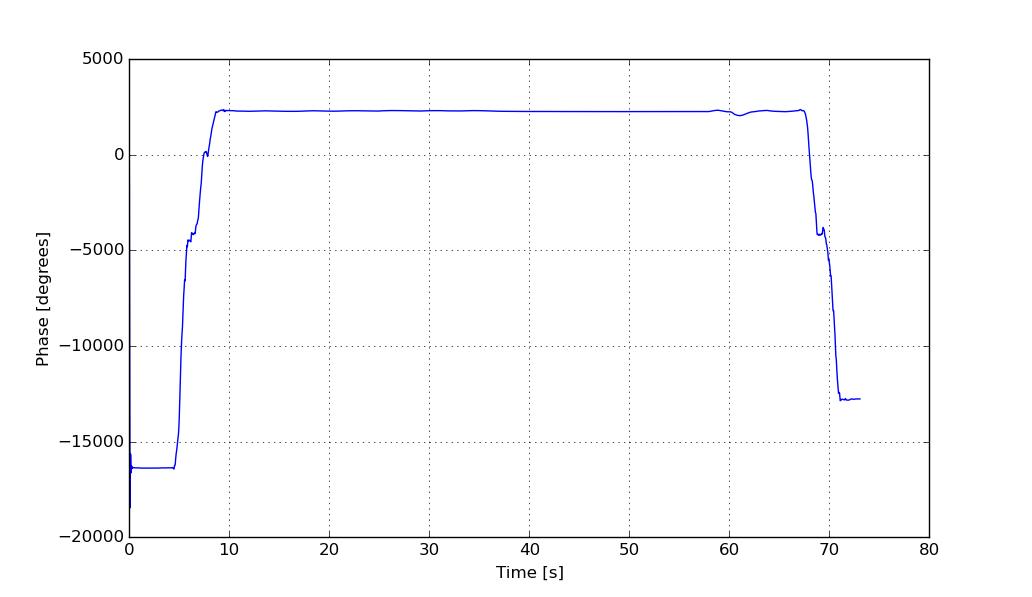
Full unwrapped phase from the recorded data.
Above is the image of the measured phase. At the beginning where I'm walking phase wraps around multiple times and the breathing signal can't be seen at this scale.
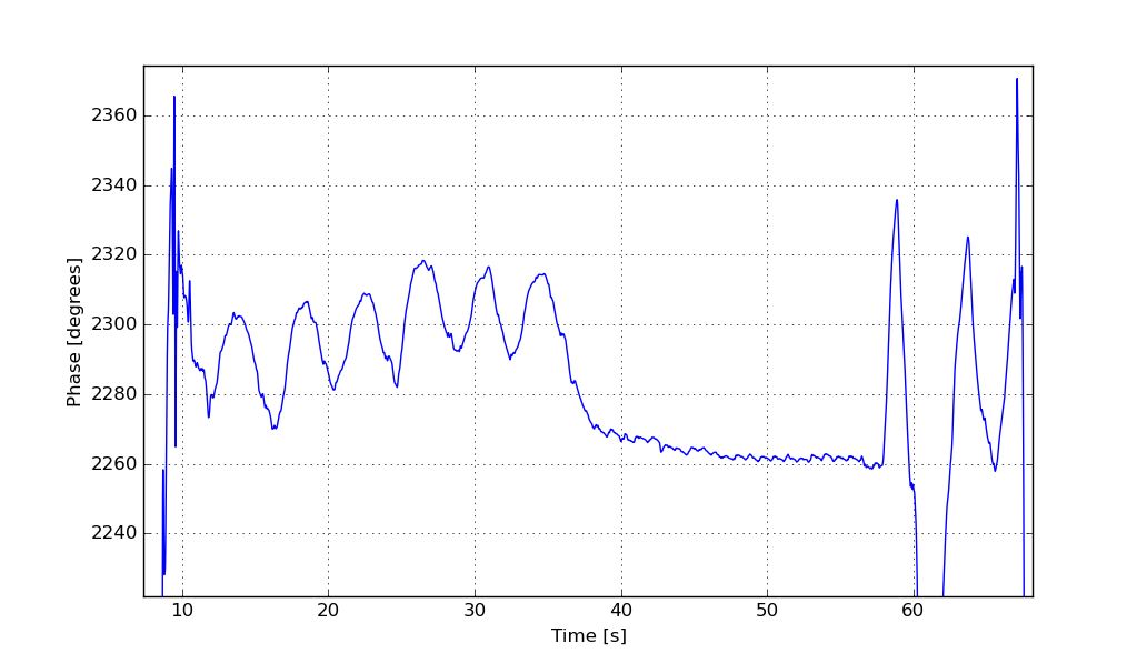
Zoomed in to breathing
Above is zoomed in to remove the walking part so that the breathing signal can be seen. Breathing amplitude is about 25 degrees, which equals 1.8 millimeters with the 5.6 GHz center frequency and breathing frequency is 0.25 Hz (15.3 breaths/min).
When I'm holding my breath signal is not completely flat, but instead a periodic signal can be seen that is caused by heart beat moving my chest a tiny amount.
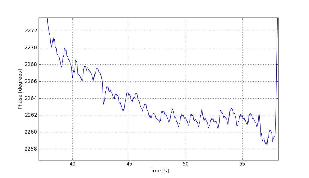
Zoomed in to heartbeats.
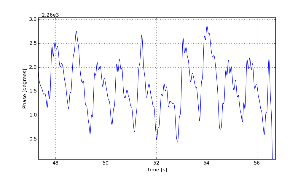
Zoomed in further to heartbeats.
Amplitude of the heartbeat signal varies a little bit because of random motions. Heartbeat frequency is 1.1 Hz (65 bpm). Amplitude is about 1 degree which translates to motion of 75 µm.
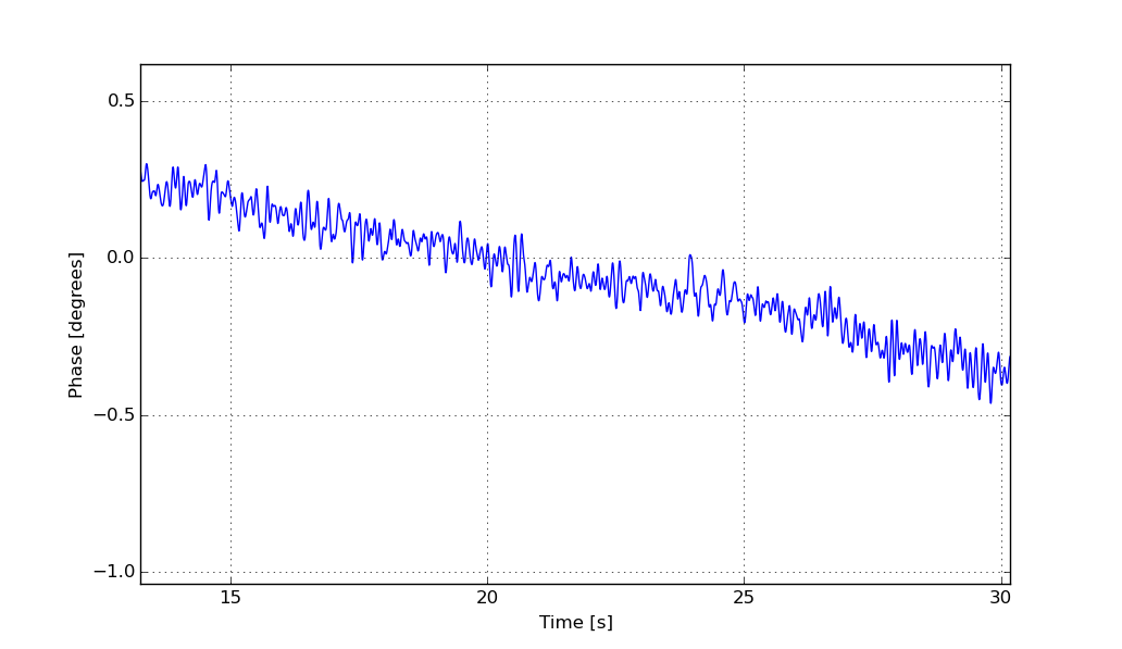
Same measurement with empty room.
Above is the result of same measurement but with empty room for measuring the phase noise. Measured noise is much lower than the heart beat signal and we can be confident that it is not noise. It should be noted that measured signal was filtered digitally with 10 Hz low pass filter to decrease the noise. Unfiltered phase noise at full bandwidth is about 1 degree RMS.
In the phase noise plot small amount of drift can be seen. Source of this drift is probably clock drift between PLL reference clock and ADC clock. Clocks are drifting tiny amount because especially the RF board uses lot of power for its small size which heats it up and when crystal is heated its frequency changes slightly. They should be derived from same clock so they wouldn't drift respect to each other, but I didn't realize it when drawing the schematics of the radar. Luckily drift is very minor and it doesn't cause many problems in normal operation.