Introduction
For background about the radar, read the article here.
Since the previous can antenna wasn't very good I made a better horn antennas. Horn antenna is a good choice for a radar antenna for many reasons most important being the very wide bandwidth and it's easy and cheap to make.
CST Model
I made few different antennas and I ended up with this small horn antenna. Aperture is 100mm x 85mm and length of the antenna is 90mm. Bigger would have been better, but would have needed more sheet metal and thus costed more.
Simulated gain is 14.4 dB and 3 dB beam width is 35 degrees. For comparison old cantennas had gain of 6 dB, beam width of 100 degrees and much higher sideband levels, so these new antennas should be significantly better increasing range and reducing clutter.
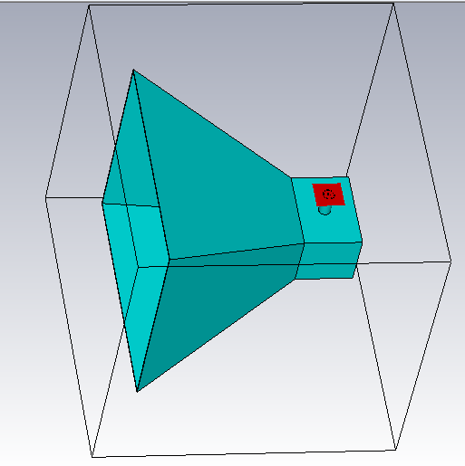
Horn antenna model in CST.
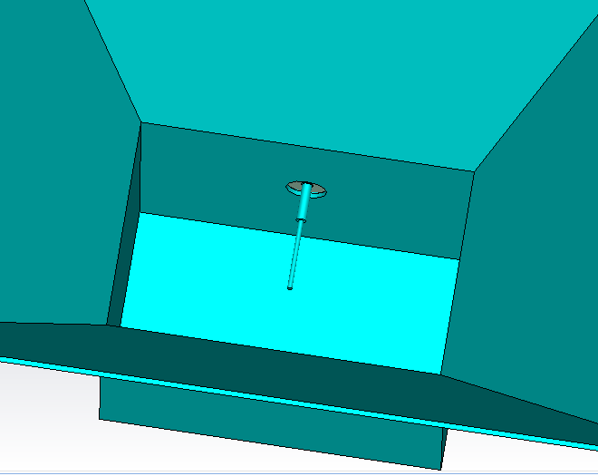
Horn antenna model in CST.

Simulated farfield radiation pattern.
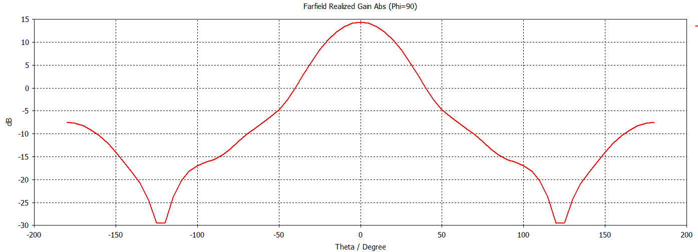
Simulated gain.
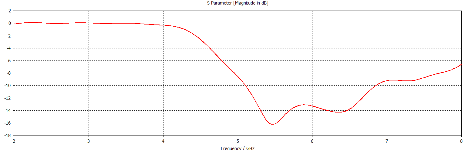
Simulated S-parameters.
Fabricated antenna
Antennas are made from 0.7mm sheet metal with pieces welded together. Quality could have been better and there is more than 2mm tolerance at some places, it is probably big enough to affect the performance. Base is made from a piece of extruded aluminium that I picked from trash.
I also put a piece of sheet metal between the antennas to reduce the antenna to antenna coupling but it didn't seem to have much effect.
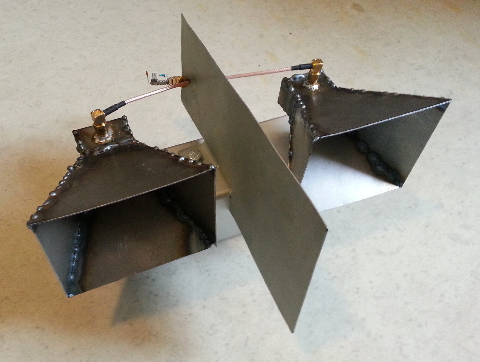
Fabricated horn antennas.
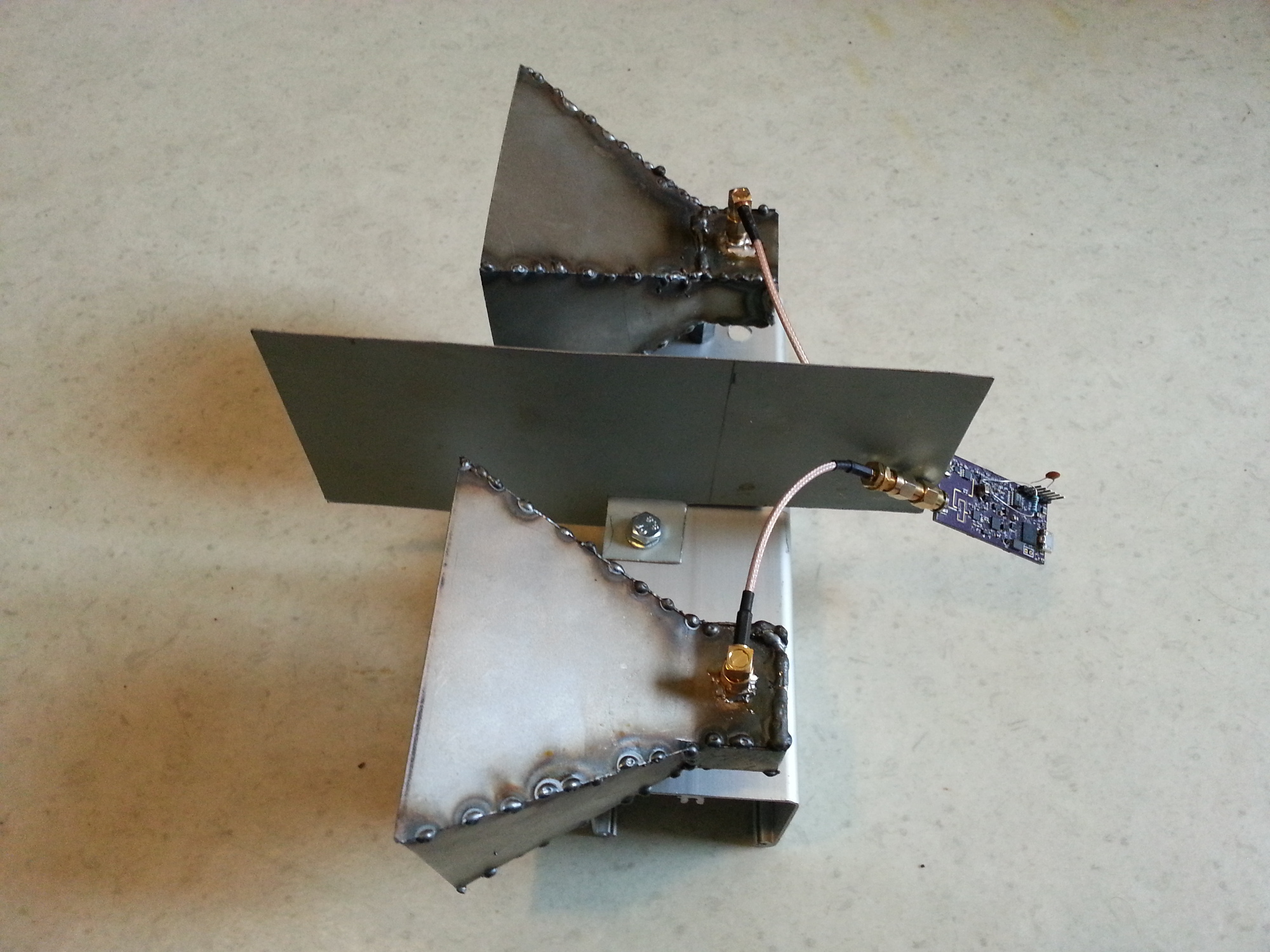
Fabricated horn antennas.
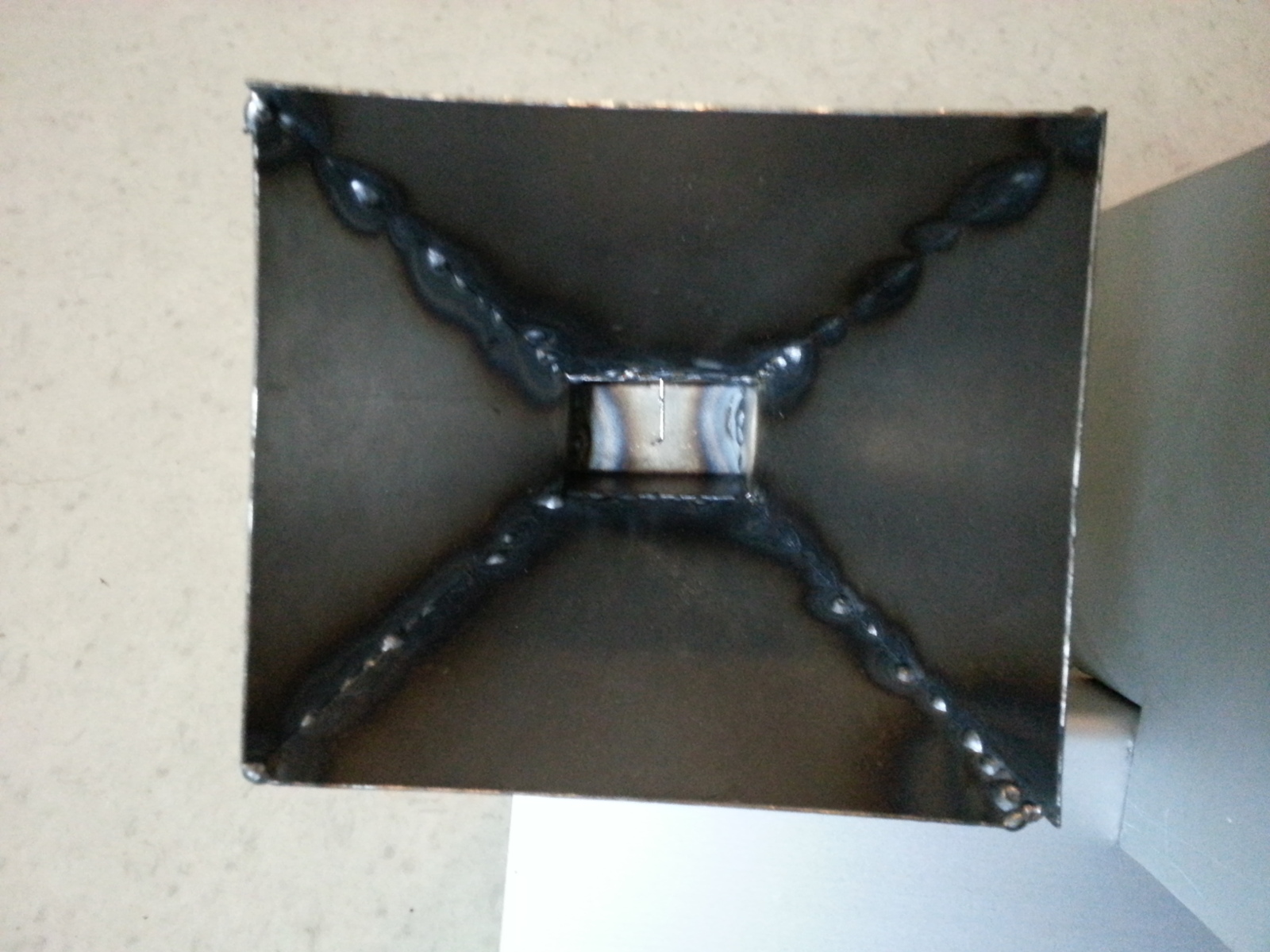
Front view. Feedline can be seen in the middle.
Measurements
I measured input reflection coefficient with a network analyzer.
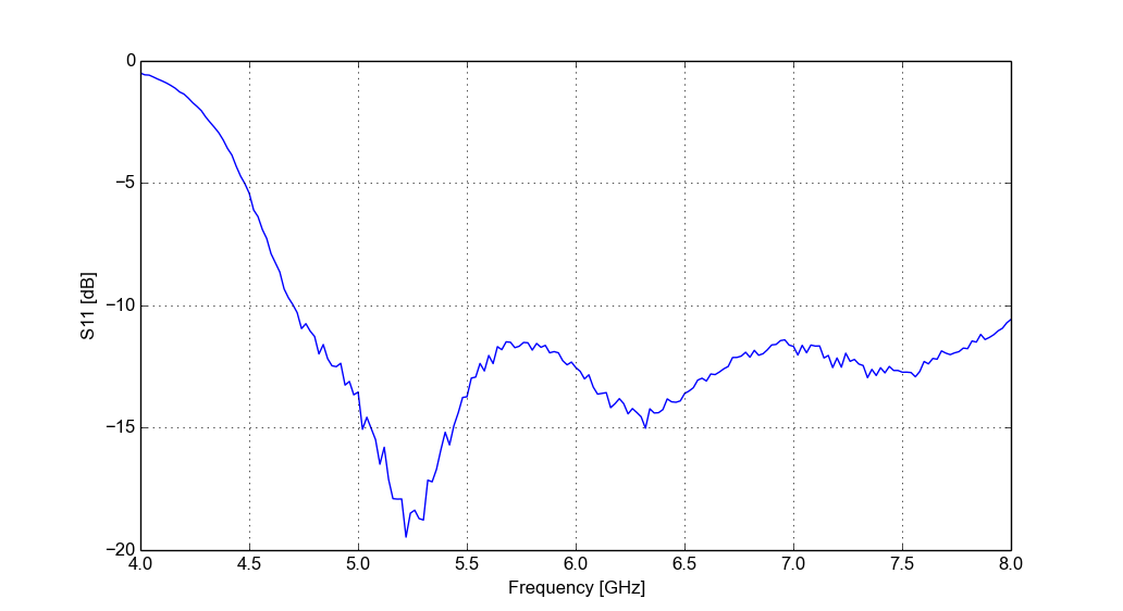
Right side antenna S11.
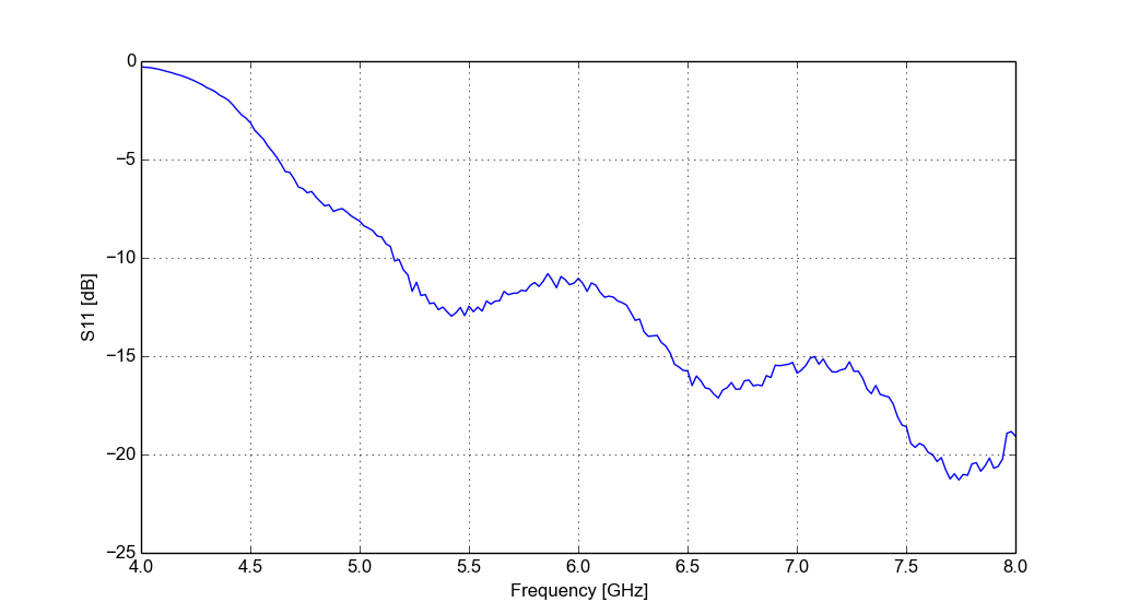
Left side antenna S11.
Due to tolerances in manufacturing there are some differences in the input reflection coefficient, but most importantly with both antennas S11 is below 10 dB for the whole usable frequency range of the radar (about 5.4 GHz to 6.1 GHz). When compared to the simulated S11 above it's clear that the shape of the curve roughly agrees, but especially at higher frequencies there are big differences with real antennas actually working better than simulated.
Tests with radar
I tested the antennas with the radar at the same football field as with the previous antennas. The goal in the middle of the field that caused the targets near 50m with old antennas was removed but the surrounding trees and fence were still there.
This time even without the clutter reduction (subtracting previous pulse to get rid of stationary targets) results are much better. Looking at the signal strength near the radar it's clear that new antennas have much higher gain. From the lack of clutter it also seems that beam width is also now much narrower. The path were I walked is clear even before the clutter reduction unlike with the previous antennas.
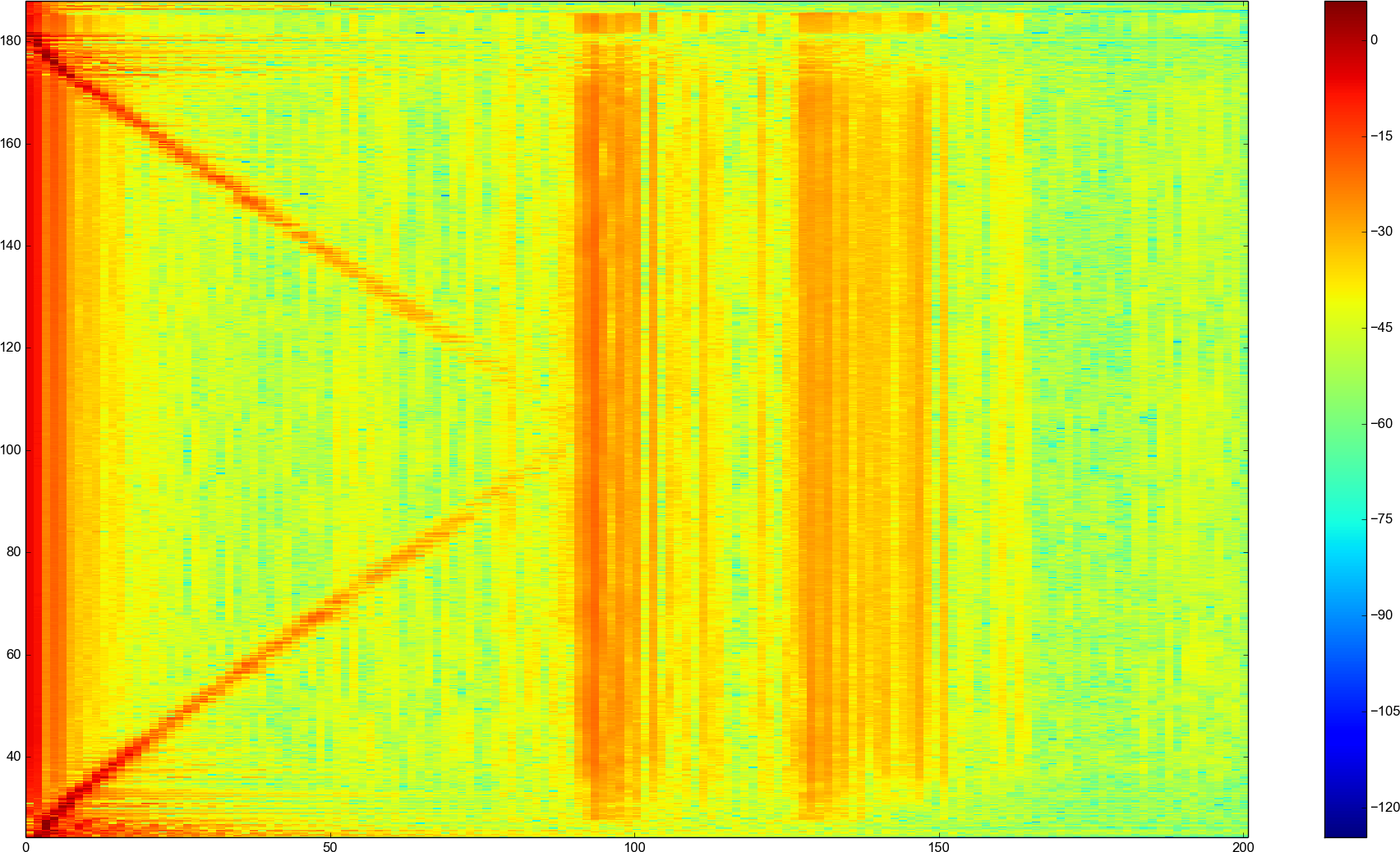
Time-range plot with new antennas and no clutter reduction
Same measurement with the old cantennas.
Measuring the beam width
To know the exact beam width better I made a measurement where I walked perpendicular to the radar beam.
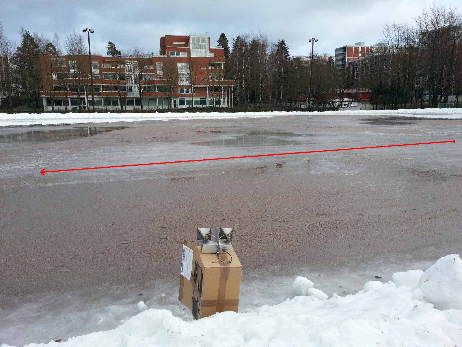
Picture of the radar and surroundings with path I walked in red.
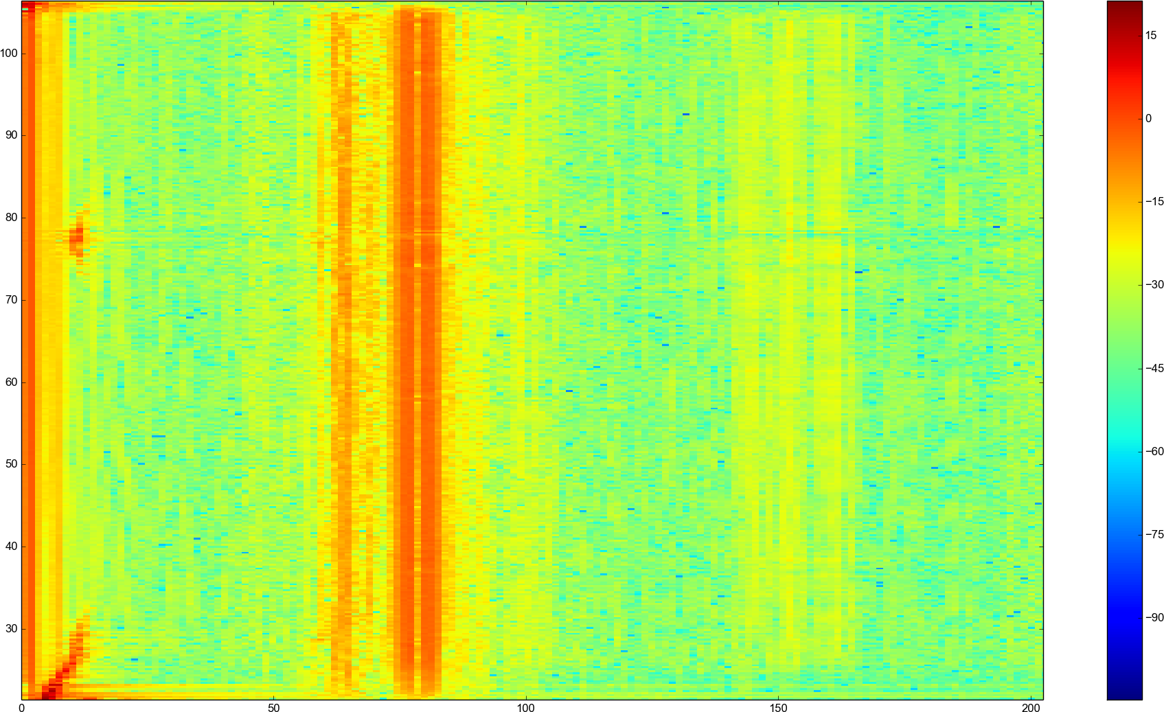
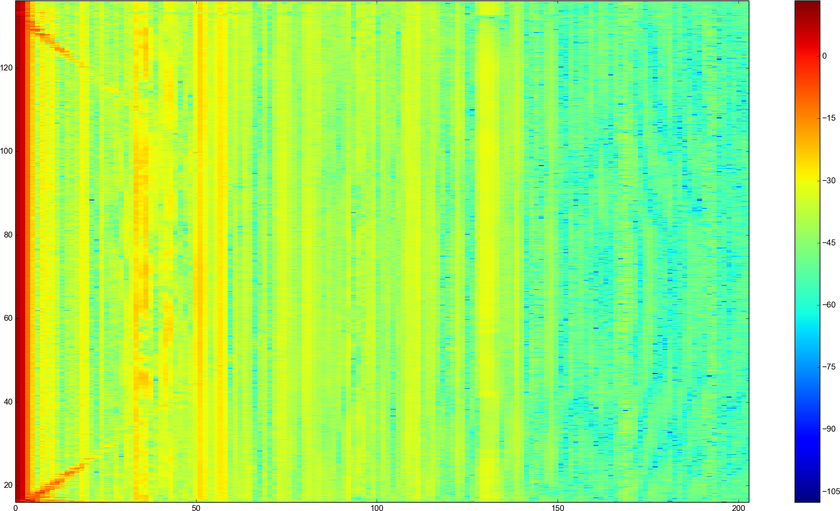
Beam size measurement results.
Above is the measurement results and near 80 second mark small red blip can be seen when I was inside the radar beam. I measured from that my walking speed is about 1.4 m/s. Time I was inside the beam such that it could be differentiated from the background was about 6.5 seconds. From the above plot we find that the distance to radar is 11 m. From these numbers we can calculate that the beam width of the radar is about 44 degrees. Since this is not 3 dB beam width but more like 10 dB beam width it agrees well enough with the simulations. For comparison beam width of the old cantennas was more than 100 degrees.
In conclusion the radar works much better with proper antennas. Range is increased, but the football field isn't long enough to test it. More importantly smaller beam width decreases the amount of clutter picked up from the surroundings and greatly increases the signal to noise ratio.