Introduction
While I was looking at some audio effect circuit schematics at the internet, I though that it would be nice to try to simulate them SPICE first and listen them, before building them to confirm if they sound good or not. But there aren't any electrical simulators that can read and output audio files, so I wrote a program using Pythons wave module, which can read a wave file and output a list of time-voltage points. Ngspice's file source device can read this big list of points and output a voltage waveform that matches the audio signal. This servers as a input for the effect circuit. To hear the output another program is needed to convert the output trace to wave file, for this too I used the Pythons wave module.
Distortion effect
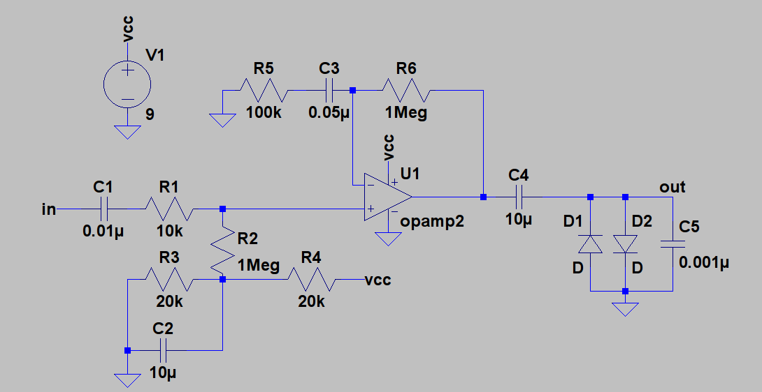
Overdrive 250 schematic.
This was one of the simpler distortion effects that I found. It's called Overdrive 250 and it's pretty popular guitar effect pedal. Schematic is from this site. Function is simple, first there is an AC-coupling capacitor and biasing circuit, because voltage supply is single sided. Op-amp is used as a non-inverting amplifier to amplify the weak input signal. R5 is really potentiometer that controls the gain. At the output there's an another AC coupling capacitor and two diodes that clip the signal. Bigger the signals amplitude is the more diodes clip and distort it.
Test audio signal is a clean guitar sound and it's from freesound.org made by user named Khoon and released under a very permissive Creative Commons 0 License, which basically says that the work is public domain.
First the output with 500k R5, which gives a milder distortion. Input amplitude matters very much, because it's multiplied by the gain of op-amp. In this recording input amplitude is 10mV. These clips are quite loud (as can be seen from the waveform), so check your output volume before hitting the play.
Decreasing R5 increases the gain and distortion:
Frequency spectrum effects of the distortion, made with audacity:
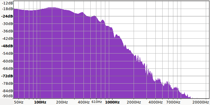
Spectrum of the clean signal.
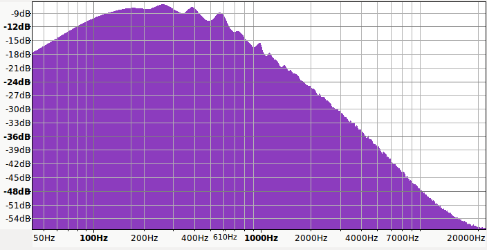
Spectrum of the harshly distorted signal.
Above are the frequency spectrums of the original clean signal and the harshly distorted signal. Difference is not that great. Some low frequency signals are filtered by the AC coupling capacitors and distortion has created new higher frequency signals. Increase of the power over the whole bandwidth is an artifact of the SPICE to wav conversion. To avoid clipping, I chose the maximum amplitude of signal to have the maximum sample value. This changes the volume of the signal.
Real circuit would probably sound slightly different, but I think this is pretty good for a simulation.
Simulation is not real time. It takes about five seconds to simulate one second
of audio at 44100Hz sampling rate. For longer simulations to save memory it's good to
save only the output waveform using save v(out) SPICE statement.
Fuzz effect
Second circuit is fuzz circuit, which is very similar to the previous distortion circuit, except op-amp is replaced by discrete transistors.
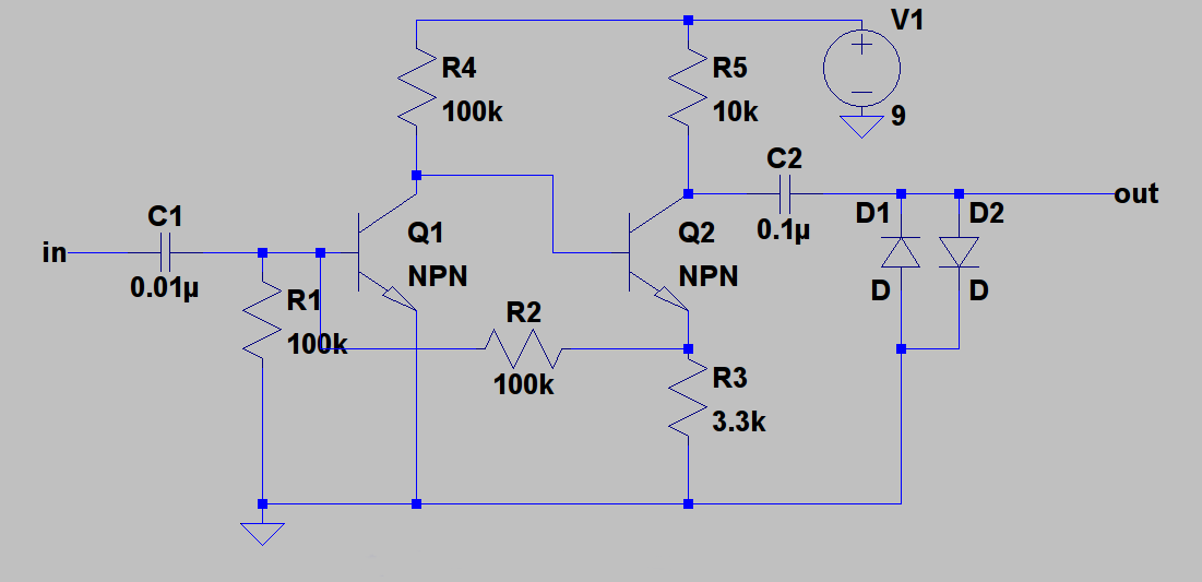
Fuzz circuit schematic. Transistors model is BC108.
This circuits output is also greatly affected by the input voltages amplitude.
This one is simulated with 1mV input amplitude:
And this one is with 10mV input:
Result is very similar to the distortion circuit, mostly because of the similar diode clipping.
Diode clipper
Waveform of the diode clipper is much smoother than I excepted it to be. Of course this also depends on the voltage of the signal and parameters of the diodes. But even this fairly smoothly clipped signal has lots of high frequency harmonics.
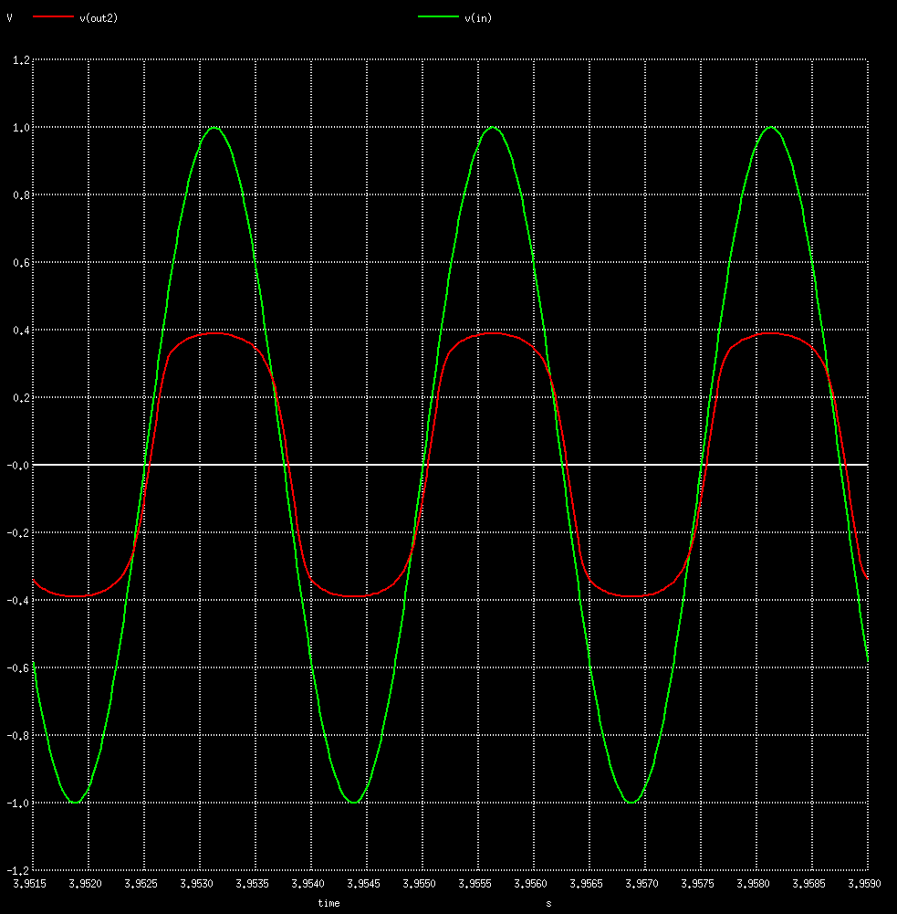
Simulation of 1V 400Hz sine wave clipped with a pair of 1N4148 diodes.
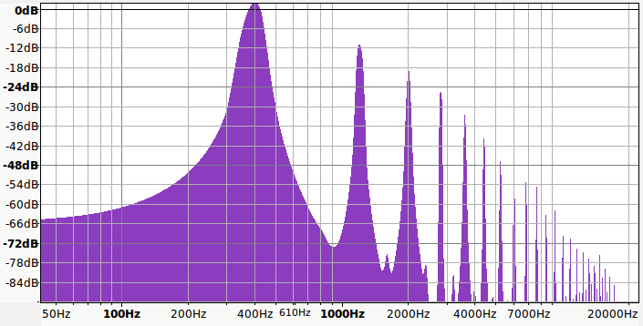
Spectrum of diode clipped sine wave.
Source code
Source code for the both of the used programs is available here.